4.2. Development
4.2.1. General Recommendations
Use a version control system like Git to keep track of your application’s source code, scripts, documentation, etc. If you accidentally brick your Jetson, you can recover quickly.
Automate everything and treat each Jetson as disposable:
Package your software in an easily-deployed format like a Docker image or a .deb package.
Automate deployment steps using something like Ansible or even just a simple Bash script.
Hint
For production uses cases, you can deploy your application to the rootfs in your L4T flashing environment. After flashing a Jetson, your application will already be deployed!
Leverage existing libraries and hardware acceleration whenever possible. Don’t reinvent the wheel unless you really need a square one!
Maximize performance using the Jetson’s MAXN or MAXN SUPER power mode. Run
jetson_clockseach boot to further maximize performance. Wait until your use case is working and nailed down before optimizing power usage.
If you run into issues, we’re always willing to help. You can reach our sales and support teams using the links below:
4.2.2. Direct Hardware Access
This section serves as a reference for users who want to interact directly with the hardware. For almost all use cases, these low-level interfaces are abstracted by our drivers thus direct interaction is not only unnecessary but not recommended.
Danger
Using the methods below to directly interact with hardware is hazardous! Applying an invalid configuration can cause transient system faults or even permanent damage. Do not use these methods unless you are absolutely confident in what you are doing.
4.2.2.1. GPIOs
General Purpose Input/Output (GPIO) refers to pins on chips that can be configured as a digital input or output. Typically, all of the low-level interactions with GPIOs are handled by D3 Embedded’s Linux kernel drivers. If you want to interact with these devices directly, there are a few options to do so:
Use the
/dev/gpiochipXinterface directly (Documentation)Use the command-line utilities provided by
gpiodwhich use the above interface
4.2.2.1.1. gpiod
To list the available GPIO drivers, use gpiodetect:
gpiodetect
gpiochip0 [tegra234-gpio] (164 lines)
gpiochip1 [tegra234-gpio-aon] (32 lines)
gpiochip2 [8-0020] (8 lines)
gpiochip3 [1-0020] (8 lines)
gpiochip4 [1-0021] (8 lines)
gpiochip5 [d3-max9295] (11 lines)
In the Linux kernel, each GPIO driver instance is assigned a unique gpiochip name. The names are assigned in the order the drivers probed in which is not deterministic meaning the GPIO chip name may change each boot.
tegra234-gpioandtegra234-gpio-aon: Tegra SoC’s GPIO pins8-0020,1-0020, and1-0021: GPIO expanders which are controlled by I2C commandsd3-max9295: Camera serializer chip which has GPIO functionality (typically used for image sensor reset line and frame sync line)
To list the available GPIO lines (pins) for each chip, run gpioinfo:
gpioinfo
gpiochip0 - 164 lines:
     line   0:      "PA.00" "regulator-vdd-3v3-sd" output active-high [used]
     line   1:      "PA.01" "status_led"  output  active-high [used]
     line   2:      "PA.02"       unused  output  active-high
     line   3:      "PA.03"       unused  output  active-high
     line   4:      "PA.04"       unused   input  active-high
     line   5:      "PA.05"       unused   input  active-high

...

gpiochip2 - 8 lines:
     line   0:  "PWDN_CAM0" "tca9554_20_outlow" output active-high [used]
     line   1:  "PWDN_CAM1" "tca9554_20_outlow" output active-high [used]
     line   2:  "PWDN_CAM2" "tca9554_20_outlow" output active-high [used]

...

gpiochip5 - 11 lines:
     line   0:      unnamed      "reset"  output  active-high [used]

...
Depending on the system’s devicetree, some lines will be unnamed while others will have descriptive names. For gpiochip0 and gpiochip1 (Tegra SoC pins), the names correspond to the pin names in the Jetson Pinmux Templates. The other gpiochips will have vendor-specific names which typically correspond to the net names in the board design’s schematic.
If the GPIO line is marked as [used], the string after the GPIO line name indicates the purpose it is being used for. In-use GPIO lines cannot be controlled by the following commands unless the driver using them is unloaded from the kernel.
For example, to command the reset GPIO of the camera (in this case an ISX028):
# Remove ISX028 driver
sudo rmmod isx

# Set GPIO low to put the ISX028 into reset (low vs. high depends on the image sensor)
# (gpiochip 5, line 0, 0 means LOW)
gpioset 5 0=0

# Pull ISX028 out of reset
# (gpiochip 5, line 0, 1 means HIGH)
gpioset 5 0=1
Note
Starting in JetPack 6.x, you may need to specify --mode=wait as an option in your gpioset command. This is required for Tegra SoC pins but may not be for other gpiochip types. Without this option, gpioset will set your requested value and then immediately restore the previous value when exiting leading to nothing happening on the wire.
To read the XERR pin on the ISX028:
# On the ISX028, we connected XERR to MFP5 (GPIO line 5 in the driver)
# The meaning of serializer chip GPIOs will be different for each image sensor
gpioget 5 5
The command will output either 1 (HIGH, no error occurred) or 0 (LOW, an error occurred).
On specific compatible pins (not all will support this), you may also use gpiomon to listen for changes to the GPIO state using interrupts (HIGH -> LOW or LOW -> HIGH). Here’s an example output of monitoring SoC GPIO ‘PI.00’ which we connected to a pulse generator:
gpiomon 0 51
event:  RISING EDGE offset: 51 timestamp: [    1234.753896370]
event: FALLING EDGE offset: 51 timestamp: [    1234.754295833]
event:  RISING EDGE offset: 51 timestamp: [    1234.787236375]
event: FALLING EDGE offset: 51 timestamp: [    1234.787282264]
event:  RISING EDGE offset: 51 timestamp: [    1234.820371673]
4.2.2.2. I2C
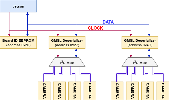
Inter-Integrated Circuit (I2C), as the name indicates, is a standard for communicating between multiple integrated circuits. It involves just two wires, a clock wire and a data wire. Each pair of clock and data wires is called a bus. On a bus, there is a single controller device which can be connected to many target devices.
The example below shows a typical I2C bus setup for D3 Embedded’s SerDes hardware. The Jetson is the controller device. The deserializers and cameras are the target devices.
Typically, all of the low-level interactions with these I2C devices are handled by D3 Embedded’s Linux kernel drivers. If you want to interact with these devices directly (e.g., to modify a register), there are a few options to do so:
Use the
/dev/i2c-Xinterface directly (Documentation)Use the command-line utilities provided by
i2c-toolswhich use the above interfaceUse a language-specific library like smbus2 for Python
4.2.2.2.1. i2c-tools
During the development process, D3 Embedded engineers generally prefer the i2c-tools utilities because they are already installed and fairly simple to use.
To list the available I2C busses, use i2cdetect:
i2cdetect -l
i2c-0        i2c             3160000.i2c                             I2C adapter
i2c-1        i2c             c240000.i2c                             I2C adapter
i2c-2        i2c             3180000.i2c                             I2C adapter
i2c-3        i2c             3190000.i2c                             I2C adapter
i2c-4        i2c             Tegra BPMP I2C adapter                  I2C adapter
i2c-5        i2c             31b0000.i2c                             I2C adapter
i2c-6        i2c             31c0000.i2c                             I2C adapter
i2c-7        i2c             c250000.i2c                             I2C adapter
i2c-8        i2c             31e0000.i2c                             I2C adapter
i2c-10       i2c             i2c-2-mux (chan_id 0)                   I2C adapter
i2c-20       i2c             i2c-2-mux (chan_id 1)                   I2C adapter
i2c-30       i2c             i2c-2-mux (chan_id 2)                   I2C adapter
i2c-40       i2c             i2c-10-mux (chan_id 1)                  I2C adapter
i2c-60       i2c             i2c-40-mux (chan_id 0)                  I2C adapter
i2c-68       i2c             i2c-2-mux (chan_id 3)                   I2C adapter
i2c-69       i2c             NVIDIA SOC i2c adapter 0                I2C adapter
The output lists each available I2C bus as well as its name. Names like 3160000.i2c indicate the bus is controlled by the Tegra SoC where 3160000 is the memory address of the specific interface controller inside the SoC. Names like i2c-2-mux indicate the bus is one of N inputs to a parent I2C mux device. The mux device may be a simple mux device or it may be a deserializer device with each camera port being an input to the mux.
To enumerate the devices on a specific bus (/dev/i2c-1 in this example), use i2cdetect with slightly different flags:
i2cdetect -y -a -r 1
     0  1  2  3  4  5  6  7  8  9  a  b  c  d  e  f
00: 00 -- -- -- -- -- -- -- -- -- -- -- -- -- -- --
10: -- -- -- -- -- -- -- -- -- -- -- -- -- -- -- --
20: UU UU -- -- -- -- -- -- 28 -- -- -- -- -- -- --
30: 30 -- -- -- -- -- -- -- -- -- -- -- -- -- -- --
40: UU UU -- -- -- -- -- -- -- -- -- -- -- -- -- --
50: -- 51 -- -- -- -- -- -- -- -- -- -- -- -- -- --
60: -- -- -- -- -- -- -- -- -- -- 6a -- -- -- -- --
70: -- -- -- -- -- -- -- -- -- -- -- -- -- -- -- --
Each cell in the table represents an I2C address that a device can respond at. Use the following list to decode the output:
UU: The address is claimed by a kernel driver. This does not indicate whether a device is actually alive or responding.28,30, etc.: A device is alive and responding at the address. No kernel driver has claimed the address.--: No device is responding at the address. No kernel driver has claimed the address.
To interact with an I2C target device, you should first read its datasheet to understand its communication protocol. Most devices use the ‘register map’ style where you first write the desired register’s address then write the new value for it or read the value. For example, to read the DEV_ID (device ID) field on a MAX9295:
# Bus 40, address 0x41, register 0x000D
i2ctransfer -y -f 40 w2@0x41 0x00 0x0D r1
You will get the output 0x91 which corresponds to the MAX9295A variant. To write 0xD3 to that same register (this won’t actually do anything because the field is read only!):
# Bus 40, address 0x41, register 0x000D, new value 0xD3
i2ctransfer -y -f 40 w3@0x41 0x00 0x0D 0xD3